4. Technical specifications
Parameter |
Value / Description |
|---|---|
Name |
DT240 |
Functionality |
multifunctional thermostat |
Temperature range |
from -55 °C to +255 °C |
Hysteresis |
from 0.1 °C to 10 °C |
Accuracy |
± 1 °C |
Mounting method |
35 mm DIN rail mount (according to EN 60715) |
Supply voltage |
100-250 V AC, 50/60 Hz |
Power supply terminals |
terminals 4-5 |
Type of internal power supply |
safety transformer galvanically isolated |
Own power consumption |
< 2 VA |
Sensor type |
NTC resistor 10/12/15/16.7/33/47/50/100 kΩ |
Sensor terminals |
terminals 6-7 |
Operating Modes |
Thermostatic (heating/cooling) Manual Timed |
Dimensions |
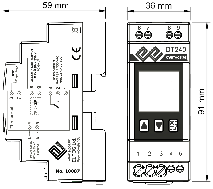
D=91mm, W=36mm, H=59mm ( 2 DIN modules ) |
Mass |
126 g |
Output |
relay contacts |
Main output terminals |
Electromechanical relay |
Main output terminals |
1 - normally closed (NC) contact (dry) 2 - normally open (NO) contact (dry) |
Maximum permissible voltage and current for the electromechanical relay |
25 A / \(\sim\ \)250 V / cosφ ≥ 0.8,
|
Mechanical endurance of contacts |
107 switching operations |
Electrical endurance of contacts |
105 switching operations |
Alarm/auxiliary output terminals |
terminals 8-9 |
Type of alarm / auxiliary output |
Electronic relay / triac (only AC voltage connections permitted) (max. 1 A, 250 Vac) |
Permitted ambient operating temperature |
-20 °C to +55 °C |
Protection rating |
IP 40 control panel IP 20 terminal blocks |
Overvoltage category |
III |
Degree of pollution |
2 |
Cross-section of connection cables |
Relay terminals ≤ 4 mm2 Other terminals ≤ 2.5 mm2 |
In accordance with the standard |
IEC/EN 60730-2-9 |


4.1. Device dimensions
4.2. Wiring diagram
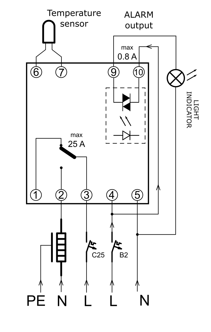
On the side of the thermostat housing, a block diagram of the thermostat connections is printed, providing sufficient information for quick and correct wiring and operation of the thermostat.
The thermostat must be supplied with power, connecting the live conductor to terminal number 4 and the neutral conductor to terminal number 5. The thermostat operates on alternating voltage, which can vary from 100 V to 250 V, while consuming a maximum of 2 VA itself.
Note
An NTC temperature sensor is connected to terminals 6 and 7; neither the order nor the colour of the wires matters. Compatible NTC sensors are: 10, 12, 15, 16.7, 33, 47, 50, and 100 kΩ / 25°C. The factory setting is a 10 kΩ NTC sensor. If using a different type of sensor, you must select the appropriate option in the settings (Settings → Temperature → Sensor Type).
Terminals 8 and 9 belong to the thermostat’s auxiliary output. This is a voltage-free output of an electronic load relay rated up to 1 A exclusively for alternating current. Depending on the thermostat settings, it can serve as an auxiliary output for control, remote monitoring, or as an alarm output signalling a fault in the regulated process.
The electronic relay output, on terminals 8 and 9, is used to open or close a circuit via this connection. Using the auxiliary output is not always necessary, nor is connecting to it.
Caution
Only alternating voltages may be connected to the alarm terminals (8 and 9).
Finally, there are terminals 1, 2, and 3. These are terminals for accepting conductors with a cross-section up to 4 mm2, which belong to the switching contact of the main electromechanical output relay. The relay’s switching capacity is 25 A at an alternating voltage of 250 V.
Note
The switching contact is voltage-free, meaning it receives no power supply from the thermostat itself. To open or close the circuit of the connected load via its switching action, an external power supply must be provided.
When controlling a heating process, the live conductor L is brought to terminal 3, and when the condition for heating operation is met, the switching contact connects to terminal 2. Therefore, the live conductor powering the load is connected to terminal 2, while the neutral N conductor of the load supply goes directly to the neutral conductor of the power source. Similarly, the protective conductor (PE) of the load is connected directly to the protective conductor of the power source without involving the thermostat.
Warning
For safety reasons, appropriate fuses or Residual Current Circuit Breaker with Overcurrent protection switches (RCBOs) must be installed in the power circuits of both the thermostat and the load.
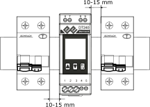
When installing the DT240 thermostat on a DIN rail, it is advisable—and mandatory when the current load on the main output relay exceeds 16 A—to leave a gap of 10–15 mm relative to adjacent equipment to ensure better cooling.