5. Thermostat operating mode
The thermostat operating mode is the device’s primary purpose and is selected at the factory. The following text describes the settings that can be changed in the thermostat operating mode.
5.1. User interface description
The simplified appearance of the DT240 thermostat’s control panel is shown in the figure below.
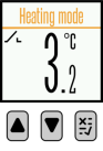
Three buttons are used to operate the device. The  button is used for up navigation and to increase numerical inputs, e.g., temperature. Similarly, the
  button is used for down navigation and to decrease numerical inputs. The third button,
  , is a multifunction button used to confirm or cancel entries, to enter the menu, and to switch the device on/off.
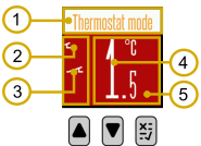
Information about the current status of the device, displayed on the screen, is divided into 5 distinct sections:
|
Status bar |
|---|---|
This section contains the status bar, which displays data in text form regarding the current state of the relay, alarms, setpoint temperature, and any detected errors (e.g., sensor error). |
|

|
Main relay status |
|---|---|
Displays the status of the main electromechanical relay. The symbol indicates that the relay’s normally open contact is closed (active), while the symbol indicates that the relay’s normally open contact is open (inactive). Additionally, depending on the heating/cooling mode, if the device is in heating mode, the symbol is displayed. If the device is in cooling mode, the symbol is displayed. |
|

|
Alarm status |
|---|---|
Displays the alarm status. The symbol indicates that an alarm is active. When no alarm is active, no symbol is shown on the display. |
|

|
Sensor temperature |
|---|---|
The value displayed on the screen is the sum of the current temperature read from the sensor and the temperature correction value set by the user (the factory default correction value is 0°C). |
|

|
Heating/cooling mode |
|---|---|
If the main relay is not active, the background colour is white. If the main relay is active and the device is in heating mode, the background colour is red. Similarly, if the main relay is active and the device is in cooling mode, the background colour is blue. |
|

5.2. Switching the device off and on
If the thermostat was previously switched on, switching it off is very simple; it is sufficient to touch the multifunction button , and two options will be displayed on the screen: Menu and Shutdown. By pressing the down button , we move the display cursor to Shutdown and confirm by touching the multifunction button , at which point the thermostat is switched off. The display will show a white symbol on a black background, internationally recognised as the ON/OFF symbol.
Note
In the event of a power loss, the device retains its previous state regarding whether it was switched on or off. The device also retains all previously entered settings.
If the device was previously switched off, a large white sign will be displayed on the black background of the thermostat screen.
If the multifunction button is touched, the message “The device is OFF.
Hold for 3s to device ON.” will appear on the display. If the multifunction button is held for 3 seconds, the message “The device is ON” and the thermostat manufacturer’s logo will appear.
Subsequently, the temperature currently measured by the temperature sensor will be displayed in the central part of the screen, and a series of scrolling, highly useful pieces of information about the operation and configuration of the thermostat will appear at the top of the screen. If the thermostat is not set to factory defaults, due to earlier adjustments made by the manufacturer or the user itself, the appearance of the screen may differ.
5.3. How to set the relay switch-on/switch-off temperatures?
In order for the thermostat to determine whether to switch the relay on or off during operation, it must have four pieces of data:
Should the thermostat operate in heating or cooling mode?
What is the current temperature of sensor TS (this data is automatically read from the temperature sensor every second).
What is the average switching temperature T1 - so-called Set temperature ?
What is the turn-on temperature difference T2 - the so-called Difference ?
As stated, the current sensor temperature reading TS will be automatically read from the sensor; however, the operating mode (heating/cooling), setpoint temperature T1 (Set temperature), and temperature differential T2 (Difference) must be manually selected or configured by the user in the thermostat options.
5.3.1. How to set temperatures in heating mode
If the thermostat is in heating mode, it will switch on the relay when the sensor temperature TS is lower than T1 - T2. The thermostat will switch off the relay if the sensor temperature TS is higher than T1 + T2. If the sensor temperature is between (T1 - T2) and (T1 + T2), the relay state remains unchanged; i.e., if the relay was previously on, it stays on, or if it was previously off, it stays off.
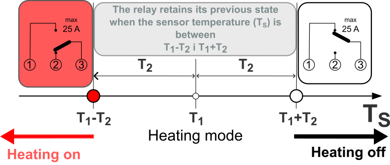
Thus, in heating mode, the rule for determining when to switch the relay on/off is:
If TS < T1 - T2, the relay is ON (sensor temperature is low, so the relay/heating turns on).
If TS > T1 + T2, the relay is off (sensor temperature is high, so the relay/heating is switched off).
If TS > (T1 - T2) and TS < (T1 + T2), the relay state does not change (sensor temperature is between (T1 - T2) and (T1 + T2)).
5.3.2. How to set temperatures in cooling mode
In cooling mode, the logic is very similar:
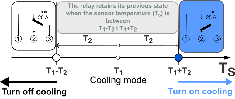
If TS < T1 - T2, the relay is off (sensor temperature is low, so the relay/cooling is switched off).
If TS > T1 + T2, the relay is on (sensor temperature is high, so the relay/cooling is switched on).
If TS > (T1 - T2) and TS < (T1 + T2), the relay state does not change (sensor temperature is between (T1 - T2) and (T1 + T2)).
Users encountering thermostat configuration for the first time may rightly ask, “Why can’t we simply enter the temperature at which the relay switches on and the temperature at which it switches off?” While this would be more intuitive for users, it would make it difficult to determine the ‘mean’ temperature being maintained, which is precisely the most critical factor in heating and cooling systems.
5.3.3. Example of determining temperatures in heating mode
Assume the thermostat must switch on the relay when the sensor temperature falls below 20°C, and switch it off when the sensor temperature rises above 28°C. This means the thermostat operates in heating mode because it prevents the sensor temperature from falling below a certain limit. In this case, the mean temperature, T1, is (28°C+20°C)/2 = 24°C, and this parameter will be set as Set temperature (T1 = 24°C). The mean value of the difference between these two temperatures, T2, is (28°C-20°C)/2 = 4°C, and this parameter will be set as Difference (T2 = 4°C).
With these two parameters, the thermostat will switch on the relay when the sensor temperature (TS) falls below (24°C-4°C) = 20°C, and switch off the relay when the sensor temperature rises above (24°C+4°C) = 28°C.
Looking at How to set temperatures in heating mode implies:
5.3.4. Example of setting temperatures in cooling mode
Assume that the thermostat must switch on the relay when the sensor temperature rises above 6°C, and switch it off when the sensor temperature falls below 2°C. This means that the thermostat operates in cooling mode because it prevents the sensor temperature from rising above a certain limit. In this case, the mean temperature, T1, is (6°C+2°C)/2 = 4°C, and this parameter will be set as Set temperature (T1 = 4°C). The mean value of the difference between these two temperatures, T2, is (6°C-2°C)/2 = 2°C, and this parameter will be set as Difference (T2 = 2°C).
With these two parameters, the thermostat will switch on the relay when the sensor temperature (TS) rises above (4°C+2°C) = 6°C, and will switch off the relay when the sensor temperature falls below (4°C-2°C) = 2°C.
If we look at How to set temperatures in cooling mode, this means:
5.4. Setting the desired temperature
The most important aspect of the thermostat is the ease and speed with which parameters related to basic temperature settings can be adjusted; therefore, Thermostat is the factory setting/factory operating mode of this device. Consequently, while the basic display screen is shown on the thermostat, it is sufficient to simply touch the down button or the up button , and the display screen Thermostat will appear, offering 3 choices: Set temperature, Difference, and Offset.
At the very beginning, the display cursor is on Set temperature; if we touch the multifunction button , a blue screen showing the previously set temperature value appears. Re-activating the multifunction button causes the temperature value to flash, indicating that the new desired temperature can be adjusted using the down button and the up button . The temperature adjustment limits depend on the currently selected temperature (NTC) sensor and whether the temperature input limit is enabled (see Setting temperature input limits). Another touch of the multifunction button switches to a new display screen, with a white background and the display cursor in the top-left corner, accompanied by the text Set temperature.
If we press the multifunction button again, the message Do you want to save
the changes? will appear on the display. We use the red button to reject the temperature change and the green one to save it. Using the down arrow buttons or up arrow buttons , we move the blue screen cursor around the green button and confirm this by pressing the multifunction button , after which the message Settings saved will appear. This indicates that the temperature change has been successfully carried out.
Tip
The procedure for changing a setting described above will be repeated for all future adjustments on this device, so it should be mastered well and remembered.
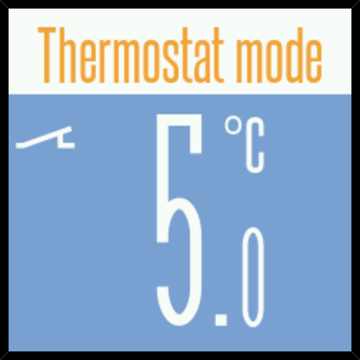
If the thermostat is in heating mode, and the newly set temperature is higher than the one currently measured by the NTC sensor, then after the time to return to the main display has elapsed, the background of the screen will turn red and the current temperature will be displayed on it. In addition, the fire symbol and the closed contact symbol will periodically alternate – as a visual warning that heating is active.
|
|
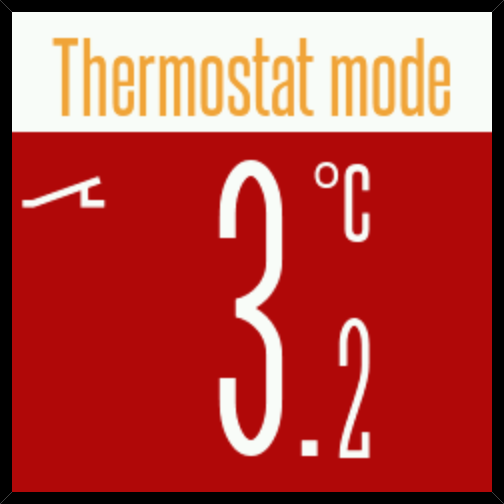
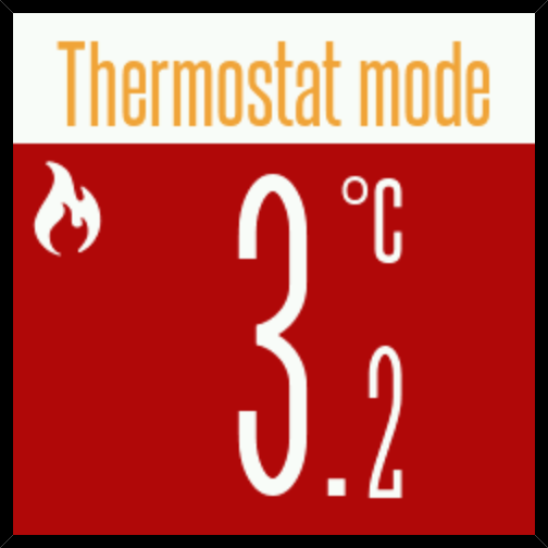
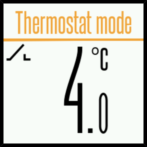
When heating reaches the desired temperature, the screen background will turn white, the fire symbol will disappear, and only the open contact symbol will appear.
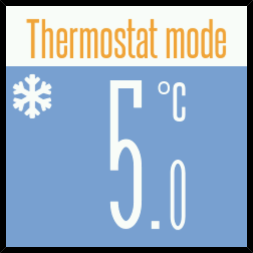
Similarly, if the thermostat is in Heat, the red screen background changes to blue, and the fire symbol changes to a snowflake symbol – to graphically indicate that the process is cooling.
|
|
Note
In this first example of adjusting a value, we can already see how important the multifunction button is, as we activated it five times, and the same will apply to almost all adjustments.
This is also an opportune moment to warn about a phenomenon that accompanies every thermostat adjustment. Whenever we begin adjusting any value on the thermostat, and if each subsequent step is not completed within a period shorter than 25 seconds, the message Menu timeout. Returning to main screen. will briefly appear on the display, and the thermostat will return to the main screen.
For example, if we attempt again to change the desired temperature (press the up button , select Set temperature, then press the button), but this time do not touch any buttons for more than 25 seconds, after the 25-second period has elapsed, the device will display the message Menu timeout.
Returning to main screen. and show the main screen with the current sensor temperature.
This function can be disabled or the return time to the main display changed, but disabling should only be used temporarily, mainly during the adjustment of thermostat settings.
5.5. Adjustment of differential
The next adjustable parameter is Difference, or the temperature difference, set in °C, at which the state of the thermostat’s output relay changes.
Please bear in mind that the selected value represents a hysteresis band of ± relative to the desired/regulated temperature setpoint (e.g., if the desired/regulated temperature is 10°C and the selected hysteresis is 0.1°C, the thermostat will switch heating on at 9.9°C and off at 10.1°C). To change the hysteresis, move the display cursor to Set temperature and press the multifunction button . A blue screen will appear showing the previously set hysteresis value. Pressing the multifunction button again causes the hysteresis value to flash, indicating that the down arrow button and up arrow button can be used to adjust the new hysteresis value. The setting range is from 0.1 to 10 °C, with a factory default of 0.5 °C. Another tap of the multifunction button switches to a new display screen with a white background, showing the newly adjusted hysteresis value. Proceed with the previously described procedure to save the new setting.
5.6. Temperature correction setting
Correction is a value that can be added to the sensor’s measured temperature before it is displayed on the screen, in order to align it with the actual temperature at the measurement location. To change this value, move the display cursor to Offset and press the multifunction button ; a blue screen showing the previously set correction amount will appear. Pressing the multifunction button again causes the correction value to flash, indicating that you can adjust the new correction using the down and up buttons. The adjustment range is from -15 to +25 °C, with a factory setting of 0.0 °C. Tapping the multifunction button once more switches to a new display screen with a white background, showing the newly adjusted correction value.
Note
Performing a correction is only meaningful if you can measure the temperature at the installation site of the DT240 thermostat’s NTC probe more accurately using another thermometer or some other measurement method.
5.7. Settings and functions menu 
If the main display showing the measured temperature is active, and you touch the multifunction button , Menu will appear with the screen cursor already positioned on option Settings. By touching the multifunction button again, you enter a sequence of possible settings that define numerous thermostat adjustments and functions, hidden behind the abbreviated names: Language, Temperature, Device, Alarm, Display, and Other.
The selection of group Language allows you to choose the thermostat’s user interface language (see Language selection).
Selection of the Temperature group allows configuration of 8 settings hidden behind abbreviated names: Set temperature, Difference, Unit, Offset, Set limit, Sensor type, Heating/Cooling and Turn-on delay.
Selection of group Device allows adjustment of 3 settings hidden behind the abbreviated names: Operating mode, Output, and Current state.
Selection of the Alarm group allows configuration of 5 settings hidden behind abbreviated names: Source, Output, Operating mode, Settings and Current state.
Selection of the Display group allows configuration of 4 settings hidden behind abbreviated names: Lock, Auto reduce, Brightness and Status bar.
Selection of the Other group allows configuration of 5 settings and access to 2 informational blocks hidden behind abbreviated names: Start screen, Menu auto exit, Help menu, Sound, Firmware, About and Factory reset.
Note
Some device setting options depend on the previously selected operating mode and are not always visible on the display!
From the aforementioned points, it is evident that thermostat operation selections and settings are numerous and difficult to describe in just one or two words; therefore, a help system has been implemented within the thermostat. It appears on the display as a textual explanation of the currently configured term or value. If the explanatory text is too long to fit on a single screen, the down key can be used to scroll through and read it completely.
Whether the thermostat displays help depends on the setting of the Help Menu option located in the Other group (see :ui3:`subMenu.other.helpmenu.name`). By default, this option is enabled as it is very useful.
How to access the help function?
When configuring certain values, the symbol appears in the top right corner of the display, leading to the help system. Positioning the display cursor over the symbol and pressing the multifunction key causes the help text to appear on the thermostat display.
5.7.1. Configuring the Temperature group
The Temperature settings group, within the Settings option, is the most commonly used. Within it, you can set: the desired temperature, differential, measurement unit, display temperature correction, thermostat operating temperature limits, sensor type, Heating/Cooling selection, and turn-on delay. The desired temperature setting (Set temperature), differential setting (Difference), and display temperature correction (Offset) have already been covered in: Setting the desired temperature, Adjustment of differential, and Temperature correction setting. The remaining settings groups are: Unit, Set limit, Sensor type, Heating/Cooling, and Turn-on delay.
5.7.1.1. Selecting the measurement unit
By moving the screen cursor to the Unit option and pressing the multifunction button , the selection screen for °C (Celsius) or °F (Fahrenheit) appears. By using the down arrow keys or up arrow keys , the blue screen cursor selects the desired unit, which is confirmed by pressing the multifunction button . A solid blue circle appears before the selected unit name. The screen cursor is then moved using the down arrow keys or up arrow keys to the top-left corner of the screen next to Unit, and the multifunction button is pressed. This is followed by the previously described procedure for saving the new setting. The factory default setting is °C (Celsius).
5.7.1.2. Setting temperature input limits
By moving the screen cursor to the option Set limit and touching the multifunction key , the screen for selecting the lower or minimum adjustable temperature (Min. value) and the upper or maximum adjustable temperature (Max. value) appears. These values are factory-set to -55°C and +255°C; however, this option serves precisely to restrict the adjustment of the desired/regulated temperature to ranges suitable for the regulated process. If we confirm the option Min. value with the multifunction key , the screen will show the selection Enable with the symbol , meaning that this setting will be ignored and the factory setting (-55°C) will apply. But if we press the multifunction key again afterwards, Enable with the confirmation checkmark symbol will briefly appear on the screen, along with a blue screen showing the currently set value of the minimum adjustable temperature. Now, activating the multifunction key causes this value to flash, which indicates that the new value can be adjusted using the down arrow keys and up arrow keys . Another touch of the multifunction key transitions to a new screen display, with a white background and the screen cursor in the top left corner, alongside the label Min. value, and here we again touch the multifunction key , after which follows the previously described procedure for saving the new setting.
To set the upper or maximum adjustable temperature, the procedure is the same, except that after selecting Set limit, use the down key to select and the multifunction key to confirm the selection Max. value.
Note
Whenever an adjustment exceeds the configured limits, a warning screen appears stating that the Min. adjustment limit or Max. adjustment limit has been reached.
|
|


5.7.1.3. Selecting sensor type
The next option for setting within the group Temperature is Sensor type. The factory setting is an Elpos NTC sensor of 10 kΩ / 25°C, and this sensor is most commonly supplied with the DT240 thermostat. However, to make the thermostat as adaptable as possible and serve as an alternative to replace previously used equipment, it is possible to select another 10 types of NTC sensors on it, namely: Elpos 12 kΩ / 25°C, Elpos 100 kΩ / 25°C, Devi 15 kΩ / 25°C, Devi 16.7 kΩ / 25°C, OJ Electronics 12 kΩ / 25°C, Eberle 33 kΩ / 25°C, Ensto 47 kΩ / 25°C, Carel/Eliwell 10 kΩ / 25°C, Carel 50 kΩ / 25°C, and Tekmar Series 31 (sensors compatible with EN50350 standard).
The corresponding NTC sensor is selected by entering the option Sensor type, moving the blue display cursor using the down keys or up keys , and confirming with the multifunction key . The selected NTC sensor will have a blue filled circle in front of its name. After that, move the display cursor to the top left corner, next to the label Sensor type, touch the multifunction key , and then proceed with the previously described procedure for saving the new setting.
5.7.1.4. Heating/Cooling Mode
Moving the display cursor to option Heating/Cooling and touching the multifunction key brings up the screen for selecting the thermostat’s purpose. The factory setting is Heat, which means the relay or relays will switch on when the NTC sensor temperature falls below the set temperature. Moving the display cursor to Cool and confirming this choice will cause the relay or relays to switch on when the NTC sensor temperature rises above the set temperature.
5.7.1.5. Turn-on Delay
Option Turn-on delay is used when you do not want to immediately switch the relay on/off (after a drop or rise in temperature), but instead wish to wait for a certain period. A delay in relay activation can be useful in cases of transient phenomena and sudden, short-term temperature fluctuations that should be ignored regarding their impact on the controlled heating or cooling process.
Moving the display cursor to option Turn-on delay opens the possibility of accepting or rejecting the use of this option. Selection is performed using the multifunction key and choosing Enable with a confirmation checkmark or with the label . Enable with the label does not actually enable the activation delay; this is the factory setting. Choosing Enable with the confirmation checkmark leads to adjusting the delay time between the temperature change and the activation of the previously selected relay or relays. The delay time can range from 2 to 10 seconds.
5.7.2. Adjusting the Device Group
The third group of settings, within the Settings option, is named Device. Within this group, the following are configured: Operating mode, Output, Current state and Mode settings (only in Manual and Time mode).
5.7.2.1. Selecting Operating Mode
Moving the display cursor to option Operating mode and touching the multifunction key brings up the screen for selecting the operating mode, which can be: Thermostat, Manual, and Time. The factory setting is Thermostat because maintaining temperature based on measurements from its own NTC sensor is the primary purpose of this device.
Manual mode and Time mode operating modes are only additional operational possibilities for this device, useful in certain situations. Descriptions of these operating modes are given in chapter Manual and time-based operating modes.
5.7.2.2. Output selection
The DT240 device has two outputs, i.e., relays. The electromechanical relay, with a switching current of 25 A, is the main output of the thermostat, represented by the label Mechanical Relay. The electronic relay, with a switching current of 1 A, is the auxiliary output of the thermostat, represented by the label Solid-state Relay.
Moving the display cursor to option Output and touching the multifunction key brings up the screen for selecting the thermostat’s relay output. Selecting individual or both relay outputs is always possible in Manual and Time modes. In Thermostat mode, Mechanical Relay is always selected, and Solid-state Relay can only be chosen if it has not already been selected for external alarm indication.
The factory setting is such that the electronic relay is used for alarms, and this can be changed via Alarm → Output → Solid-state Relay. After selecting a specific relay, symbolised by a confirmation checkmark , or non-use of a specific relay, symbolised by the sign , follow the previously described procedure for saving the new settings.
5.7.2.3. Output status
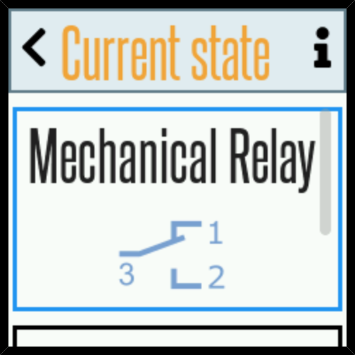
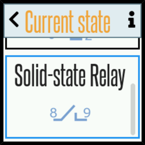
Moving the display cursor to option Current state and touching the multifunction key displays a graphical representation of the current position of the contacts of the main electromechanical relay. If the semiconductor relay is not used as an external alarm output and is selected as the auxiliary relay, a graphical representation of the contact state on terminals 8 and 9 of the thermostat will also appear.
|
|
5.7.3. Alarm group adjustment
The fourth group of settings, within the Settings option, is Alarm. Within this group, the following are configured: Source, Output, Operating mode, Settings and Current state.
Note
When Manual or Time-based mode is selected, the Alarm group is not available.
5.7.3.1. Alarm source
By moving the screen cursor to Source and touching the multifunction button , an event selection screen appears for activating the alarm. The factory default is that the alarm always activates in the event of a break or short circuit in the NTC sensor, indicated by the name Sensor error. The other two options: Low temp and High temp can be selected by moving the cursor to them and confirming with the multifunction button . This will result in a confirmation checkmark appearing before these names. Confirming Low temp as the alarm reason means that an alarm will occur if the temperature falls below the set point. Confirming High temp as the alarm reason means that an alarm will occur if the temperature rises above the set point. All three alarm reasons can be selected.
Once alarms for low and/or high temperature are enabled, it is necessary to enter the temperature values at which the alarm(s) will activate.
The temperatures at which Low temp and/or High temp activate the alarm are adjusted in: Alarm → Settings → Set temperature (see Setting alarm activation temperature ).
5.7.3.2. Alarm output selection
By moving the screen cursor to option Output and touching the multifunction button , a screen appears where, using the down buttons or up buttons , you can select Solid-state Relay and/or Internal buzzer, and then confirm with the multifunction button what is included upon alarm activation. Selecting Internal buzzer will cause an audible signal produced by the thermostat itself to sound when an alarm occurs. Selecting Solid-state Relay will close contacts 8 and 9 (load capacity up to 1 A) of the thermostat when an alarm occurs, which can then be used for any notification or external acoustic and/or visual signalling.
5.7.3.3. Alarm mode
By moving the screen cursor to option Operating mode and touching the multifunction button , a screen appears where, using the down ▼ or up ▲ buttons, you can select Continuous or Time, and then confirm the desired choice with the multifunction button . The process of saving the new settings proceeds in the usual manner.
Selecting Continuous means that the alarm, when activated, will remain continuously on (e.g., the buzzer sounds continuously), while selecting Time means that the alarm will be on/off according to a predefined period (e.g., 5 seconds on, 10 seconds off) – see Alarm on time and Alarm off time .
5.7.3.4. Alarm settings
By moving the screen cursor to option Settings and touching the multifunction button , a screen appears where, using the down buttons or up buttons , you can select, and then confirm with the multifunction button : Delay, Silent, Buzzer volume, Set temperature (only in Thermostat mode).
5.7.3.4.1. Alarm off time
Option Off time is visible on the screen only if the alarm mode is set to Time mode. Selecting this option leads to adjusting the duration of the alarm off-period in time mode. The adjustment and saving of the new setting proceed in the usual manner.
5.7.3.4.2. Alarm on time
Option On time is visible on the screen only if the alarm mode is set to Time mode mode. Selecting this option leads to adjusting the duration of the alarm on-period in time mode. The adjustment and saving of the new setting proceed in the usual manner.
Both times can be adjusted within a range of 1 to 600 seconds.
5.7.3.4.3. Delay
Selecting option Delay and confirming Enable allows entering the delay time from the moment of alarm detection to the moment of activating the internal buzzer and/or electronic relay (adjustment limits are from 5 to 60 seconds).
5.7.3.4.4. Silent mode
Silent mode is an alarm operating mode in which the alarm will automatically mute after a predefined OFF time has elapsed, and will automatically reactivate (if there is a reason for the alarm) and remain active for the specified ON time.
Selecting Silent and confirming Enable allows entering ON and OFF times. ON is the alarm on-time, and OFF is the alarm off-time. Both times can be adjusted within limits of 5 to 600 minutes, with factory settings being 5 minutes of alarm on-time and 10 minutes of alarm off-time.
After the set off time has elapsed, the alarm sounds again. The fault message is constantly displayed on the thermostat screen.
5.7.3.4.5. Buzzer volume
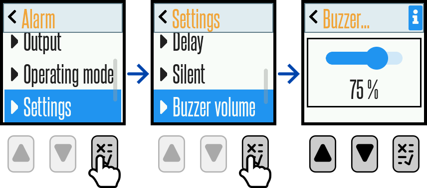
By moving the screen cursor to Buzzer volume and touching the multifunction button , a screen appears displaying a slider and sound volume percentage. Touching the multifunction button enables, and using the down buttons and up buttons adjusts, the sound volume within the range of 25% to 100%. The sound volume is also visualised by the movement of the slider, and the selection is confirmed by touching the multifunction button . As with all previous examples of adjusting a setting, the usual procedure for saving the change made must be performed here. The factory default sound volume setting is 75%.
5.7.3.4.6. Setting alarm activation temperature
If Low temp and/or High temp are selected as alarm Source within group Alarm, the values at which the alarm will activate are configured here.
By moving the screen cursor to Set temperature and touching the multifunction key , a screen appears where, using the down or up keys, you can select Min. value or Max. value, and then confirm the selection with the multifunction key .
When the selection of Min. value is confirmed, the alarm processing for Low temp is set, meaning that the alarm will activate if the sensor temperature drops below the entered value. The minimum possible value is –55°C.
When the selection of Max. value is confirmed, the alarm hysteresis for High temp is set, meaning the alarm will activate if the sensor temperature drops below the entered value. The maximum possible value is 255°C.
5.7.3.5. Alarm output status
By moving the screen cursor to the option Current state and touching the multifunction button , a graphical representation of the current status of alarm outputs – internal buzzer and/or electronic relay (if selected as an alarm output) – appears on the display.
Screen appearance when the buzzer and electronic relay are not enabled:
Screen appearance when the buzzer and electronic relay are enabled:
5.7.4. Display group settings
Within the Display group, the following are configured: Lock, Auto reduce, Brightness and Status bar
5.7.4.1. Device lock and password
By moving the screen cursor to Lock and touching the multifunction button , the enable (Enable ) or disable () device settings lock screen appears. The selection is made by touching the multifunction button . If the selection is confirmed (Enable ), the screen Password appears, which has 3 boxes for digits. The factory password is 1, 2, 3. Each digit can be changed from 0 to 9 using the down arrow keys or up arrow keys . After entering a digit, the entry must be confirmed using the multifunction button .
Important
The factory password is 1 2 3
The purpose of locking is to prevent unauthorised or incompetent persons, who should not know the password and thus have the opportunity to compromise the correct operation of the heating or cooling process, from changing device settings.
After entering and confirming your own password, manual locking is performed by simultaneously pressing the down arrow button and the up arrow button while the main display is active on the device. Alternatively, automatic locking occurs after a preset time interval. The display shows the information Display locked.
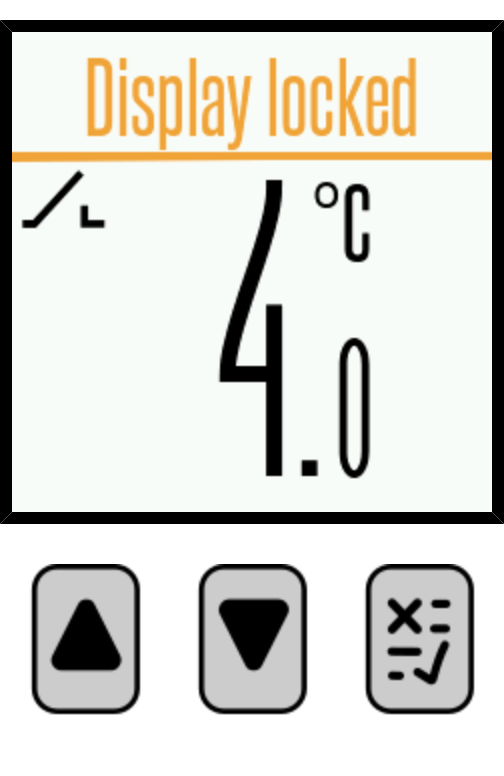
If automatic lock is to be used, it is set immediately after entering the password. By pressing the down key , the scrolling display Enable automatic locking opens, where the multifunction key can be used to select or deselect or automatic lock. If automatic lock is selected, a new display appears where it is chosen whether this lock will be Visible () or not ().
Being visible means that a line will appear at the bottom of the main display, which will shrink to indicate the passing of the last 10 seconds before locking. After choosing visibility or invisibility, there is still the setting of the time after which automatic locking will occur. This time can range from 30 to 300 seconds, with the factory setting being 60 seconds but not activated.
5.7.4.2. Device unlocking
When the main display screen is active on the device and the multifunction button is pressed, the message Display locked. Hold for 3s to enter password will appear on the display. After holding the multifunction button for 3 seconds, a screen for entering a three-digit password will appear. Using the multifunction button and the down arrow buttons or up arrow buttons , enter and confirm your own password, after which the screen with the message Display unlocked will appear.
Warning: If automatic locking was previously enabled, it will occur again after the time set for automatic locking has elapsed. The message Display locked will briefly appear on the display and will subsequently appear as a scrolling information in the Status bar. If an incorrect password is entered, a warning message Incorrect password will be displayed.
Important
If you forget your password, you can reset it to the factory value by pressing the and buttons.
It is necessary to press the button quickly at least 10 times, and then immediately press the button quickly at least 10 times.
5.7.4.3. Automatic reduction of brightness intensity
By bringing the display cursor to Auto reduce and touching the multifunction button , the screen for enabling (Enable ) or disabling () automatic reduction of display brightness appears. The selection is made by touching the multifunction button . If the selection is confirmed, the next screen shows the time after which the brightness will be reduced. This time is adjustable within a range of 5 to 60 seconds. The factory setting is 30 seconds.
5.7.4.4. Brightness
By bringing the screen cursor to Brightness and touching the multifunction button , a screen displaying the slider and the percentage of screen brightness intensity appears. Touching the multifunction button enables the function, and the down ▼ and up ▲ buttons adjust the brightness in the range from 25% to 100%. The brightness level is visualised by the movement of the slider, and the selection is confirmed by touching the multifunction button . As with all previous examples of setting certain parameters, the usual procedure for saving the changes made must be carried out here.
5.7.4.5. Status bar
The last, but very useful setting within the Display group is named Status bar. What is the status bar? It is a bar visible at the very top of the main display screen, through which very useful information about operating mode, mode settings and other important data scrolls.
By positioning the screen cursor on Status bar and touching the multifunction button , a screen appears offering the selection of 4 data items to be displayed, namely: Set temp., Relay, Alarm out and Alarm error. Selection is performed by activating the multifunction button and adding a confirmation checkmark before the selected data item for display.
Selection of Set temp. displays the desired heating or cooling temperature.
Selection of Relay displays the status of the main relay output (ON / OFF).
Selection of Alarm out shows the current alarm state (ON / OFF).
Selection of Alarm error describes errors that caused an alarm (No error / Error: Sensor shorted / Error Error: Sensor disconnected).
The factory setting is such that all 4 data items are enabled for display in the status bar.
Note
The status bar also displays some other information, depending on how the device is configured. Some of these are: Display locked, Thermostat mode, Heating mode, Manual mode, Main out : OFF, Main out : ON, Time mode, Aux. out : ON , Aux. out : OFF , Set ON time , Set OFF time .